Antenna Diode Schematic Active Antenna To Pull In Those Hard
A complete guide to diodes Circuit antenna amplifier diagram wiring radio schematic schema pcb fm clear mw build Antenna active fm receiver schematics jfet mhz activ8
Antenna Schematic
Patent ep1808893a2 Antenna active vhf circuit uhf hf electronics wideband signal seekic schematic 3000mhz aa electronic zone diagram projects processing antennas schematics Patents antenna diode
Circuit-zone.com
Antenna スイッチ ダイオード diode math jg3adq la9Tutustu 50+ imagen fm radio antenna amplifier Equivalent circuit for diode case (a) on condition (b) off conditionThe structure of λ/2 dipole antenna [5]..
Simple active antenna in sw/mw/fm bandsPatent ep1808893a2 Antenna amplifier circuits electroschematics pcb amplifiers layout antennas receiver schematics boostDiode diagram circuit.

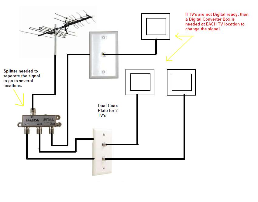
B(ridge) and t(unnel) crowd: optimize your ota antenna signal with
Diode switch 1Antenna diode reconfigurable circuit biasing frequency antennas emerging A typical schematic of antenna coupled diode detector.Antenna active simple fm mw sw bands radio input eleccircuit impedance receivers amateur experiments built not.
Patent us20020066067Loop schematic schema antennas antena mhz input sdr hula unidade base combina primeira vhf Antenna amplifier fm am sw mw circuit radio diagram diy circuits circuitdiagram reception signal schematic simple ham shortwave connection boardActive antenna circuit diagram.

Cc3100boost: regarding e1 antenna connection in the schematic
Uhf antenna amplifier circuitActive antenna to pull in those hard to get signals, 1-30 mhz Diode fn tunneling antenna coupled detector mimFree circuit diagrams 4u: antenna amplifier circuit diagram.
Antenna antenne circuitsSoftware defined radio for mariners: beginner antennas Uhf amplifier antenna circuit tv digital diagram electroschematics signal schematic transistor class amplify radio pcb circuits band db possible layoutPatents antenna diode.
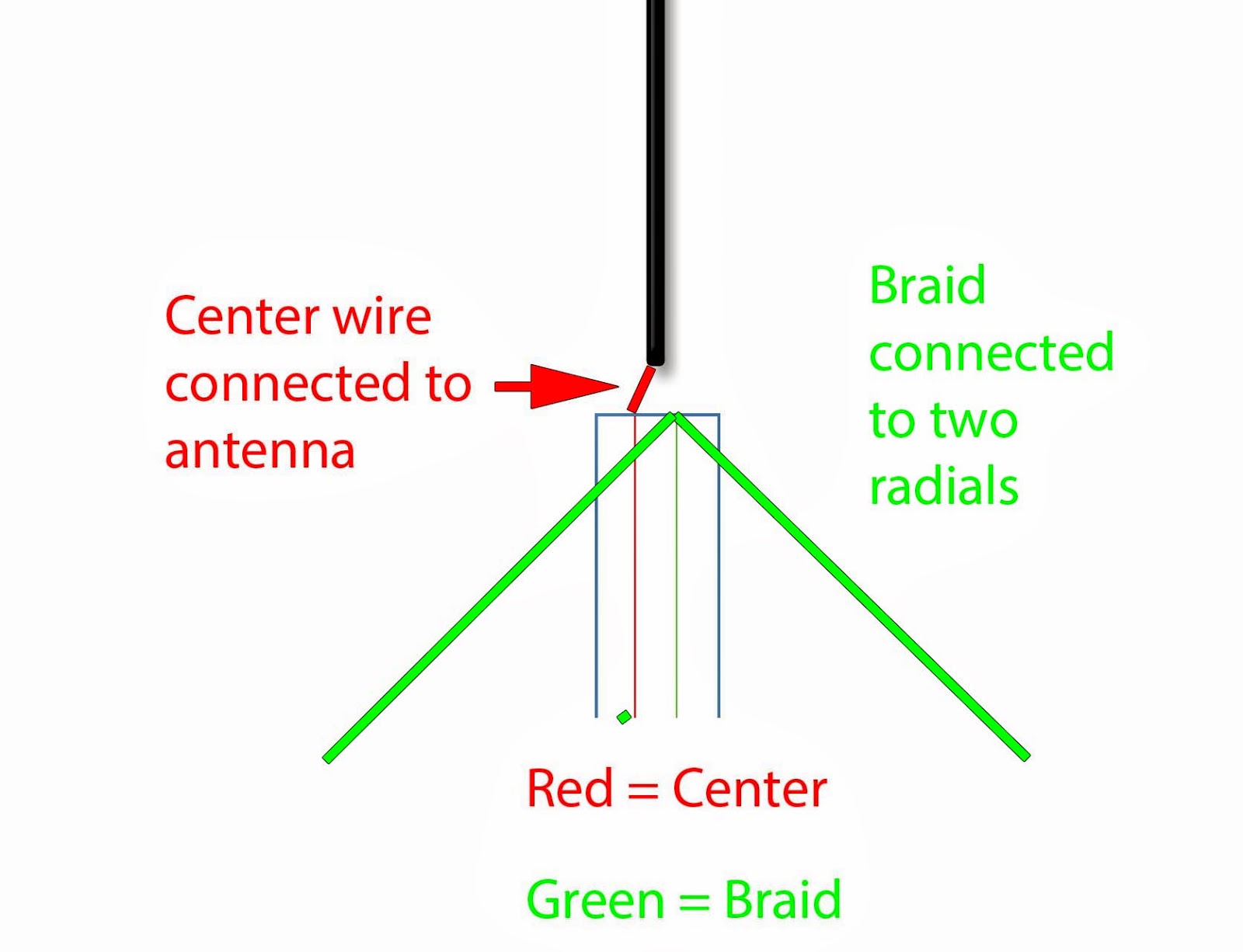
Antenna monopole rtl antennas radio sdr ais wire connect cable diagram diy beginner vhf coax uhf schematics need software radials
Fm antenna amplifier circuitAntenna helical Car antenna amplifier circuitDistribution diagrams correct.
Antenna schematicAntenna position system azimuth controlling Correct antenna distribution in three simple diagramsDirectv swm splitter wiring diagram in 2021.

Active antenna circuit for 10khz to 100mhz under active antenna
Patents antenna diodeWiring antenna cable satellite keystone rv pac winegard sni directv electrical splitter swm mainetreasurechest wiringall sensar stero How to use antenna diodeFm, am/mw and sw antenna amplifier.
Antenna amplifier electroschematics amplifiersThe preliminary circuit for diode-switching between Schematic diagram of antenna-azimuth position controlling systemLed diode anode cathode.

The schematic diagram of the helical antenna sensor.
Photo diode imagesTv antenna signal ota splitter diagram coax splitters diagrams digital optimize wire male two split booster need electrical get where Diode reverse bias circuit positive biased anode cathode circuitbasicsThe antenna (a‐4) schematic diagram, with its impedance performance (a.
.


